


What Our Customers Are Saying
SKU
SM24A-MP-TP
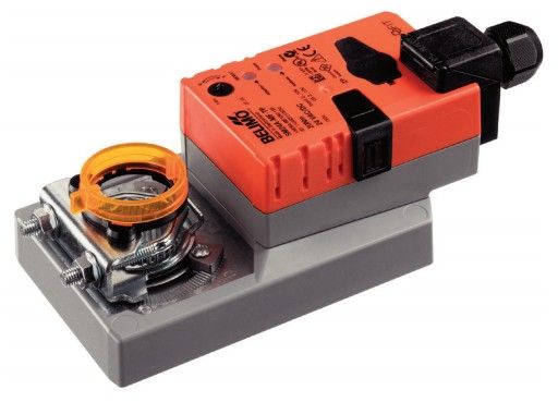
SM24A-MP-TP Damper Actuator, 20 Nm, AC/DC 24 V, 150 s
£247.80
£206.50
On request
Next Supplier Stock Update: 18/10/2026
Manuals & Datasheets
| DATASHEET |
 |
| IP rating | IP54 |
| Input Signal | 0..10 Vdc, MP-BUS |
| Manufacturer | Belimo |
| Power Supply | 24Vac/Vdc |
| Torque | 20 Nm |
| Running time | 140 to 150 sec |
| Actuator type | Rotary |
| Control Type | Modulating |
SM24A-MP-TP Damper Actuator, 20 Nm, AC/DC 24 V, 150 s
- Damper actuator
- 20 Nm, 150 s adjustable
- AC/DC 24 V, modulating, MP-Bus
- IP54, manual override can be locked
- Operating range DC 2...10 V, 0...32 V adjustable
- Position feedback DC 2...10 V, 0...10 V, adjustable
- Connection terminals IP54
- Selectable direction of rotation (right/left)
- Angle of rotation limitation mech. + electron. adjustable
Mode of operation: Conventional operation: The actuator is connected with a standard modulating signal of DC 0...10V and drives to the position defined by the positioning signal. The measuring voltage U serves for the electrical display of the actuator position 0...100% and as slave control signal for other actuators. Operation on the MP-Bus: The actuator receives its digital positioning signal from the higher level controller via the MP-Bus and drives to the position defined. Connection U serves as communication interface and does not supply an analogue measuring voltage.
Converter for sensors: Connection option for a sensor (passive or active sensor or switching contact). The MP actuator serves as an analogue/digital converter for the transmission of the sensor signal via MP-Bus to the higher level system.
Parameterisable actuators: The factory settings cover the most common applications. Single parameters can be modified with the Belimo Service Tools MFT-P or ZTH EU.
Simple direct mounting: Simple direct mounting on the damper spindle with an universal spindle clamp, supplied with an anti-rotation device to prevent the actuator from rotating.
Manual override Manual override with push-button possible (the gear is disengaged for as long as the button is pressed or remains locked).
High functional reliability: The actuator is overload protected, requires no limit switches and automatically stops when the end stop is reached.
Adjustable angle of rotation: Adjustable angle of rotation with mechanical end stops.
Home position: The first time the supply voltage is switched on, i.e. at the time of commissioning, the actuator carries out a synchronisation. The synchronisation is in the home position (0%). The actuator then moves into the position defined by the positioning signal.

Adaption and synchronisation: An adaption can be triggered manually by pressing the “Adaption” button or with the PC-Tool. Both mechanical end stops are detected during the adaption (entire setting range). Automatic synchronisation after pressing the gearbox disengagement button is configured. The synchronisation is in the home position (0%). The actuator then moves into the position defined by the positioning signal. A range of settings can be adapted using the PC-Tool (see MFT-P documentation)
Electrical data:
- Nominal voltage AC/DC 24 V
- Nominal voltage frequency 50/60 Hz
- Nominal voltage range AC 19.2...28.8 V / DC 21.6...28.8 V
- Power consumption in operation 3.5 W
- Power consumption in rest position 1.4 W
- Power consumption for wire sizing 6 VA
- Connection supply / control Terminals 4 mm² (cable Ø 4...10 mm, 4-wire)
- Parallel operation Yes (note the performance data)
Functional data:
- Torque motor Min. 20 Nm
- Torque variable 25%, 50%, 75% reduced
- Positioning signal Y DC 0...10 V
- Positioning signal Y note Input impedance 100 kΩ
- Control signal Y variable Open-close 3-point (AC only) and Modulating (DC 0...32 V)
- Operating range Y DC 2...10 V
- Operating range Y variable Start point DC 0.5...30 V and End point DC 2.5...32 V
- Position feedback U DC 2...10 V
- Position feedback U note Max. 0.5 mA
- Position feedback U variable Start point DC 0.5...8 V and End point DC 2.5...10 V
- Position accuracy ±5%
- Direction of motion motor Selectable with switch 0 / 1
- Direction of motion note Y = 0 V: At switch position 0 (ccw rotation) / 1 (cw rotation)
- Direction of motion variable Electronically reversible
- Manual override Gear disengagement with push-button, can be locked
- Angle of rotation Max. 95°
- Angle of rotation note can be limited on both sides with adjustable mechanical end stops
- Running time motor 150 s / 90°
- Motor running time variable 86...346 s
- Adaption setting range manual
- Adaption setting range variable No action
- Adaption when switched on Adaption after pushing the gear disengagement button
- Override control MAX (maximum position) = 100%, MIN (minimum position) = 0% and ZS (intermediate position, AC only) = 50%
- Override control variable MAX = (MIN + 32%)...100%, MIN = 0%...(MAX – 32%) and ZS = MIN...MAX
- Sound power level motor 45 dB(A)
- Spindle driver Universal spindle clamp reversible 10...20 mm
- Position indication Mechanically, pluggable
Safety:
- Protection class IEC/EN III Safety extra-low voltage
- Protection class UL UL Class 2 Supply
- Degree of protection IEC/EN IP54
- Degree of protection NEMA/UL NEMA 2, UL Enclosure Type 2
- EMC CE according to 2004/108/EC
- Certification IEC/EN IEC/EN 60730-1 and IEC/EN 60730-2-14
- Certification UL cULus according to UL 60730-1A, UL 60730-2-14 and CAN/CSA E60730-1:02
- Mode of operation Type 1
- Rated impulse voltage supply / control 0.8 kV
- Control pollution degree 3
- Ambient temperature -30...50°C
- Non-operating temperature -40...80°C
- Ambient humidity 95% r.h., non-condensing
- Maintenance Maintenance-free
Weight: approx. 1.10 kg
