


What Our Customers Are Saying
SKU
SRF24A-SR-S2
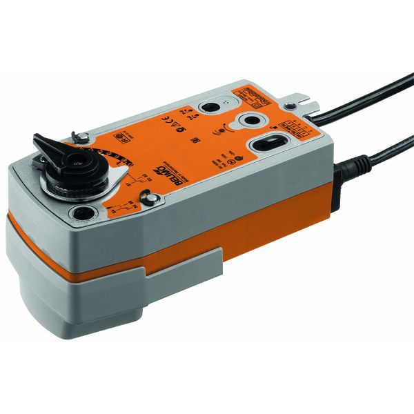
SRF24A-SR-S2 Spring-return actuator NC, 20 Nm, AC/DC 24 V, 90 s - Belimo | ideal for ball valves and butterfly valves
£375.48
£312.90
On request
Next Supplier Stock Update: 18/10/2026
Manuals & Datasheets
| DATASHEET |
 |
| Product type | Actuator |
| IP rating | IP54 |
| Manufacturer | Belimo |
| Power Supply | 24Vac/Vdc |
| Torque | 20 Nm |
| Running time | 90 to 105 sec |
| End Switches | 2 End Switches |
| Fail Safe | Spring Return |
| Ideal for | ball valves, butterfly valves |
At IACS we provide Free Delivery and Next 1-2 day Delivery for all the Belimo Actuators in stock.
The Belimo SRF24A-SR-S2 is an Actuator used in HVAC applications and air ventilation systems.
The Torque force applied by the SRF24A-SR-S2 is 20 Nm.
The power supply requested for this Rotary Actuator is 24Vac/Vdc.
IACS has the best prices on the right Belimo Actuators for your system.
Consult the Belimo custom datasheet above or contact iacs via email for personalised assistance if you have queries about size or installation.
SRF24A-SR-S2 Spring-return actuator NC, 20 Nm, AC/DC 24 V, 90 s
- Spring-return actuator NC
- 20 Nm, 90 s, 90°
- AC/DC 24 V, modulating, 2 x SPDT
- IP 54, Manual override with integrated position stop
- Running time spring < 20 s
- Control DC 0...10 V
- Operating range DC 2...10 V
- Position feedback DC 2...10 V
- Connection PVC cable 1m
- Auxiliary switch 2 integral
- Emergency control closed
- with mounting kit for RKH mounted
Mode of operation: The actuator is connected with a standard modulating signal DC 0...10 V. The actuator moves the valve to the operating position at the same time as tensioning the return spring. The valve is turned back to the emergency position by spring force when the supply voltage is interrupted.
Direct mounting: Simple direct mounting on the rotary valve or butterfly valve with mounting flange. The mounting orientation in relation to the fitting can be selected in 90° steps.
Manual override: Manual actuation of the valve with manual elevator crank, engagement with the locking switch at any position. Unlocking is manual or automatic by applying the operating voltage.
High functional reliability: The actuator is overload protected, requires no limit switches and automatically stops when the end stop is reached.
Adjustable angle of rotation: Adjustable angle of rotation with mechanical end stop.
Flexible signalization: The actuator has one auxiliary switch with a fixed setting and one adjustable auxiliary switch. They permit a 10% or 11...90% angle of rotation to be signaled.
Electrical data:
- Nominal voltage AC/DC 24 V
- Nominal voltage frequency 50/60 Hz
- Nominal voltage range AC 19.2...28.8 V / DC 21.6...28.8 V
- Power consumption in operation 5.5 W
- Power consumption in rest position 3 W
- Power consumption for wire sizing 8.5 VA
- Auxiliary switch 2 x SPDT, 1 x 10% / 1 x 11...90%
- Switching capacity auxiliary switch 1 mA...3 (0.5) A, AC 250 V
- Connection supply / control Cable 1 m, 4 x 0.75 mm²
- Connection auxiliary switch Cable 1 m, 6 x 0.75 mm²
- Parallel operation Yes (note the performance data)
Functional data:
- Torque motor Min. 20 Nm
- Torque spring return Min. 20 Nm
- Positioning signal Y DC 0...10 V
- Positioning signal Y note Input impedance 100 kΩ
- Operating range Y DC 2...10 V
- Position feedback U DC 2...10 V
- Position feedback U note Max. 0.5 mA
- Position accuracy ±5%
- Direction of rotation motor Y=0 (0V = A - AB = 0%)
- Direction of rotation spring-return Deenergised NC, valve closed (A - AB = 0%)
- Manual override By means of hand crank and locking switch
- Angle of rotation 90°
- Running time motor 90 s / 90°
- Running time emergency setting position < 20 s / 90°
- Sound power level motor max. 45 dB(A)
- Position indication Mechanical
- Service life Min. 60,000 emergency positions
Safety:
- Protection class IEC/EN III Safety extra-low voltage
- Protection class UL UL Class 2 Supply
- Protection class auxiliary switch IEC/EN II Protective insulated
- Degree of protection IEC/EN IP54
- Degree of protection NEMA/UL NEMA 2, UL Enclosure Type 2
- EMC CE according to 2004/108/EC
- Low voltage directive CE according to 2006/95/EC
- Certification IEC/EN IEC/EN 60730-1 and IEC/EN 60730-2-14
- Certification UL cULus according to UL 60730-1A, UL 60730-2-14 and CAN/CSA E60730-1:02
- Mode of operation Type 1.AA.B
- Rated impulse voltage supply / control 0.8 kV
- Rated impulse voltage auxiliary switch 2.5 kV
- Control pollution degree 3
- Ambient temperature -30...50°C
- Non-operating temperature -40...80°C
- Ambient humidity 95% r.h., non-condensing
- Maintenance Maintenance-free
Weight: Approx. 2.6 kg
Customers Also Bought
