


What Our Customers Are Saying
SKU
SY4-230-MP-T
SY4-230-MP-T THIS PRODUCT HAS BEEN PHASED OUT, PLEASE CONTACT SALES TEAM FOR REPLACEMENT
On request
Next Supplier Stock Update: 17/10/2026
Manuals & Datasheets
| DATASHEET |
 |
| Product type | Actuator |
| IP rating | IP67 |
| Input Signal | 0..10 Vdc, MP-BUS |
| Manufacturer | Belimo |
| Power Supply | 230Vac, 1Ph, 50Hz |
| Torque | 400 N |
| Running time | Quick (2.5 to 20 sec) |
| Actuator type | Rotary |
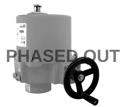
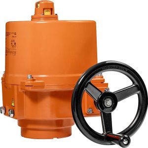
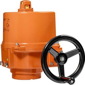
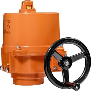
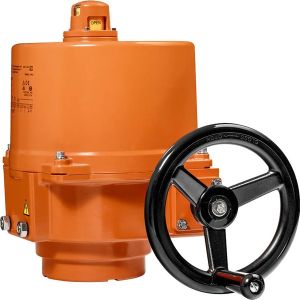
SY4-230-MP-T Rotary actuator butterfly valve, 400 Nm, AC 230 V, 18 s
- Rotary actuator butterfly valve
- 400 Nm, 18 s, 90°
- AC 230 V, 138 VA, modulating, MP-Bus, 2 x SPDT
- IP 67, Manual override with handwheel
- Operating range DC 2...10 V, 0...32 V adjustable
- Position feedback DC 2…10 V, 0...10 V adjustable
- Position indication: Yes
- Auxiliary switch 2 x integrated
- Terminal connection
- with square adapter, screw set F10 f.butterfly valves D6..
Principle of operation: Conventional operation: The actuator is connected with a standard modulating signal and travels to the position defined by the positioning signal. The measuring voltage U serves for the electrical display of the actuator position 0 ... 100% and as slave control signal for other actuators. Operation on the MP-Bus: The actuator receives its digital positioning signal from the higher level controller via the MP-Bus and travels to the position defined. Connection U serves as communication interface and does not supply an analogue measuring voltage.
Parameterisable actuators: The factory settings cover the most common applications. Input and output signals and other parameters can be altered with the BELIMO Service Tool, MFT-P.
Simple direct mounting: Simple direct mounting on the butterfly valve. The mounting orientation in relation to the butterfly valve can be selected in 90° (angle) increments.
Manual override: The butterfly valve can be closed (turn clockwise) and opened (turn anticlockwise) with the handwheel. The handwheel does not move while the motor is running.
Internal heating: An internal heater prevents condensation buildup.
High functional reliability: Mechanical end stops limit the actuator to –2° and 92°. The internal limit switches interrupt the voltage supply to the motor. In addition, a motor thermostat provides overload protection and interrupts the voltage supply if the actuator is used outside of the specified temperatures.
Combination valve/actuator: Refer to the valve documentation for suitable valves, their permitted medium temperatures and closing pressures.
Signalling: The integrated auxiliary switches are equipped with a gold/silver coating that permits integration both in circuits with low currents (mA range) and in ones with larger-sized currents (A range) in accordance with the specifications in the data sheet. It should be noted with this application however that the contacts can no longer be used in the milliampere range after larger currents have been applied to them, even if this has taken place only once.
Electrical data:
- Nominal voltage AC 230 V
- Nominal voltage frequency 50/60 Hz
- Nominal voltage range AC 207...253 V
- Power consumption in operation 120 W
- Power consumption in operation note incl. heating
- Power consumption in rest position 5 W
- Power consumption for wire sizing 138 VA
- Current consumption 0.6 A
- Auxiliary switch 2 x SPDT, 1 x 3° / 1 x 87°
- Switching capacity auxiliary switch 1 mA...5 (3 inductive) A, DC 5 V...AC 250 V
- Connection supply / control Terminals 2.5 mm² (Wire 2 x 1.5 mm² or 1 x 2.5 mm²)
- Parallel operation Yes (note the performance data)
Functional data:
- Torque motor 400 Nm
- Positioning signal Y DC 0...10 V
- Positioning signal Y note Input impedance 100 kΩ
- Operating range Y DC 2...10 V
- Operating range Y variable Start point DC 0.5...30 V and End point DC 2.5...32 V
- Position feedback U DC 2...10 V
- Position feedback U note Max. 0.5 mA
- Position feedback U variable Start point DC 0.5...8 V and End point DC 2.5...10 V
- Position accuracy ±5%
- Manual override Temporary with handwheel (non-rotating)
- Angle of rotation 90°
- Angle of rotation note Internal limit switch, not adjustable
- Running time motor 18 s
- Duty cycle 75 % (= active time 18 s / operating time 24 s)
- Sound power level motor 70 dB(A)
- Position indication Mechanically (integrated)
Safety:
- Protection class IEC/EN I Protective earth
- Protection class auxiliary switch IEC/EN I Protective earth
- Degree of protection IEC/EN IP67
- EMC CE according to 2004/108/EC
- Low voltage directive CE according to 2006/95/EC
- Mode of operation Type 1
- Control pollution degree 4
- Ambient temperature -30...65°C
- Non-operating temperature -30...80°C
- Ambient humidity 95% r.h., non-condensing
- Maintenance Maintenance-free
Mechanical data:
Connection flange F10
Weight: Approx. 22 kg
Materials: Housing material Aluminium pressure casting
Customers Also Bought
