
What Our Customers Are Saying
How to Commission a HVAC Variable Flow System
10
Jun
Before You Start: Pre-Commissioning Checks
Variable flow commissioning cannot succeed on a system that is mechanically incomplete. Before starting any hydraulic or electrical work, confirm all pipework is complete and pressure-tested to the design test pressure. All AB-QM flow limiters must be pre-set and all strainers installed with clean mesh elements. The distribution pump VSD must be installed, wired, and powered. Room temperature sensors and BMS wiring must be complete to the zone controllers or FCU controllers.
For a full foundational overview of HVAC control strategy, see the HVAC Controls Practical Guide.
Obtain the commissioning schedule, the document that lists every terminal's design flow rate in l/h, the AB-QM DN and the flow setting ring position for each. If this has not been produced by the design engineer, calculate it before going near the system: Q (l/h) = Load (kW) × 860 ÷ ΔT (K).
✓ Pre-setting AB-QM flow limiters during off-site kitting, before the valves go into the pipework, is best practice. The setting ring can be adjusted in the field without removing the valve, but doing it systematically before installation reduces commissioning time significantly and ensures every setting is recorded.
Step 1: Setting AB-QM Flow Limiters
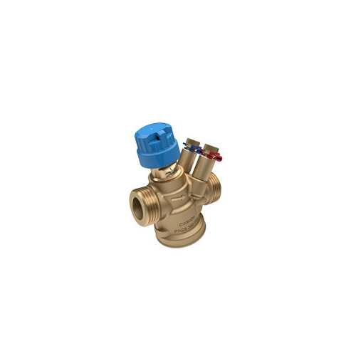
For each terminal, locate the AB-QM DN size and the terminal's design flow in l/h. Open the Danfoss AB-QM product datasheet and find the calibration scale for that specific DN, DN15, DN20, DN25, DN32, DN40 and DN50 each have a different numbered scale. Rotate the setting ring to the scale position that corresponds to the design flow. Record the setting ring number in the commissioning schedule alongside the design flow and the valve location. Repeat for every terminal on the system before any water is introduced.
⚠ Never use one DN calibration scale for a different DN valve. The scales are not proportional to each other, a setting of 4 on a DN15 and a setting of 4 on a DN20 are completely different flow rates.
Step 2: System Fill and Venting
Fill the system from the lowest point with the correct inhibited water treatment for the pipework materials, consult the building specification and water treatment strategy. Use automatic air vents at all high points, but do not rely on them alone: manual venting at all high-point tundishes and FCU coils is essential on first fill. Air locks in PICV systems produce symptoms, low flow, unstable DP readings, apparent AB-QM underperformance, that exactly mimic insufficient system pressure, and lead engineers to incorrectly increase pump speed as the first response.
Once the system is filled and static, pressurised to the design cold fill pressure, check all joints for leaks before starting the pump. Record fill pressure.
Step 3: Pump Start and DP Verification
Start the distribution pump at minimum speed. Allow the system to stabilise and re-vent any air that has been disturbed. Increase pump speed gradually. Measure differential pressure at the index circuit, the terminal or branch that is most hydraulically remote from the pump, where DP will be lowest. At design flow conditions, confirm DP at the index terminal exceeds 15 kPa.
The 15 kPa minimum is the AB-QM activation threshold, below this value the DP regulator is not active and each AB-QM behaves as a plain globe valve with no flow limiting. If index DP is below 15 kPa, increase pump DP setpoint or investigate pressure losses on the index branch (strainers, undersized pipework, partially closed isolating valves).
Set the VSD pump DP setpoint to maintain 20–25 kPa at the index terminal at design load, providing a margin above the 15 kPa minimum while not over-pressurising the system. Document the pump DP setpoint, the index terminal DP measurement, and the pump speed at design conditions.
Step 4: Electrical and BMS Commissioning
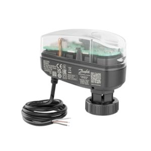
With hydraulics proven, commission the BMS control loops. Apply 100% demand to each zone in turn via the BMS and confirm the AB-QM actuator drives to fully open (10V at the Y terminal for a 0–10V actuator). Confirm the actuator is reaching full stroke, the actuator position feedback signal (typically a 2–10V output on the Y2 terminal of the AME 110NL or AME 120NL) should read the equivalent of full open. Measure flow at the terminal, at full demand and correct hydraulics, flow should equal the pre-set maximum flow rate.
Apply 0% demand and confirm the actuator drives to closed. Record the actual closed position and confirm there is no significant flow through the terminal, an improperly seated actuator or an air-locked valve that reads closed on the actuator but is physically held open by a trapped air bubble is a common fault at this stage.
Step 5: Control Loop Tuning and Stability Testing
Once each individual terminal is proven mechanically and electrically, commission the zone temperature control loops. Starting values for FCU zone temperature control: proportional band 2–3°C, integral time 400–500 s, derivative off. Run the zone through a heating or cooling cycle and observe the temperature response on BMS trend. The zone temperature should approach setpoint smoothly, overshoot by no more than 1°C, and settle within 10–15 minutes under steady load.
If the zone hunts, temperature oscillates around setpoint and the valve cycles continuously, the most likely cause is proportional gain too high or valve Kvs too large for the load. Widen the proportional band first. If the zone is sluggish, temperature approaches setpoint slowly and never quite reaches it, reduce integral time (increase gain) and check there is no mechanical issue with the valve reaching full stroke.
Step 6: Commissioning Documentation
Sign-off documentation for a PICV system should include: the commissioning schedule with every AB-QM setting ring position and corresponding design flow; measured pump DP at the index terminal; measured DP across each AB-QM at full demand; BMS trend data showing zone temperature stability under load; and the water treatment records including inhibitor dose and pH at fill. This documentation forms part of the O&M manual and is required for BESA DW/TM2 compliance.
Frequently Asked Questions
Q: How do I know if the AB-QM is working correctly?
Measure DP across the terminal at full demand, should be above 15 kPa. Measure flow, should equal the pre-set maximum setting. Confirm the actuator is receiving the correct signal and reaching full stroke. These three checks confirm the PICV, actuator and hydraulics are all functioning correctly.
Q: What if I can't achieve 15 kPa at the index terminal?
Check strainers on the index branch first, a partially blocked strainer can reduce available DP significantly. Check all isolating valves on that branch are fully open. Check pump DP setpoint. If none of these resolve it, review the pipe sizing on the index branch against the design calculations.
Q: Can I commission a PICV system without a flow metre?
Yes, the AB-QM's pre-set flow limiter means measured flow at each terminal should equal the design flow when DP is above 15 kPa and the actuator is fully open. A clamp-on ultrasonic flow metre at the index branch confirms overall flow rather than individual terminal flow. Individual terminal verification is done by confirming DP and actuator stroke.
Comment(s)
Recent Posts
-
EC Fans versus AC Fans Explained: Which Is Right for Your HVAC System
 October 17, 2026
 -
Steam Humidifier Explained: How HygroMatik Humidification Systems Work
 October 16, 2026
 -
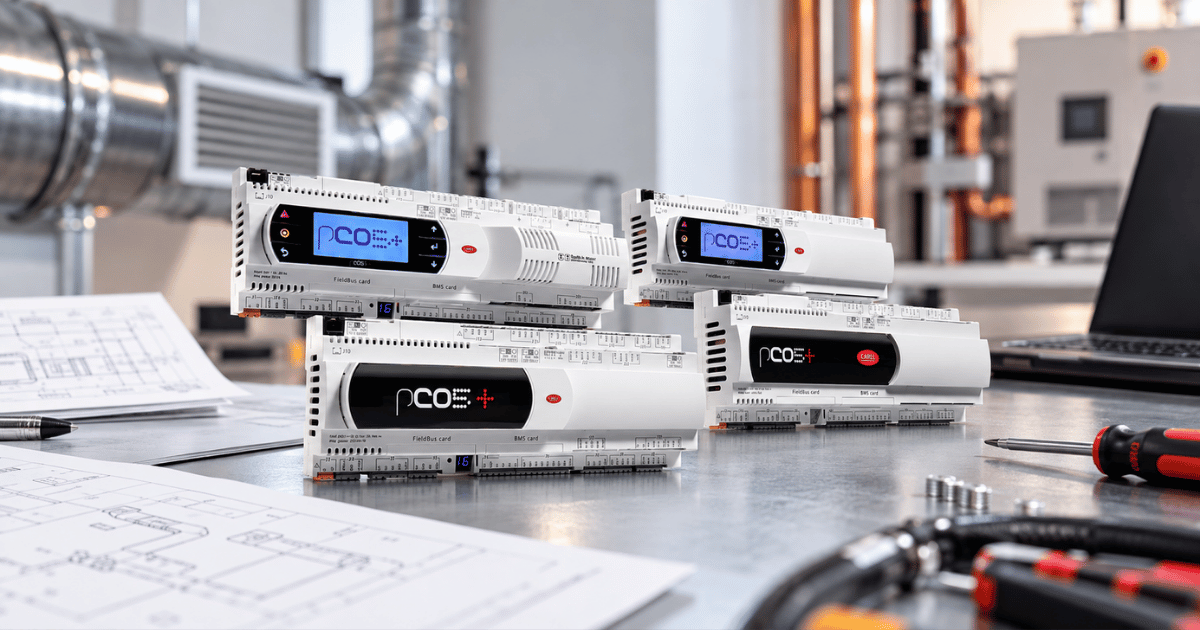
Carel Controller Fault Codes Explained: A Troubleshooting Guide
 October 15, 2026
 -
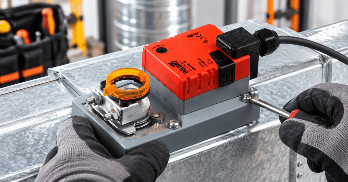
Damper Actuator Not Working? How to Diagnose and Fix Common Faults
 October 2, 2026
 -
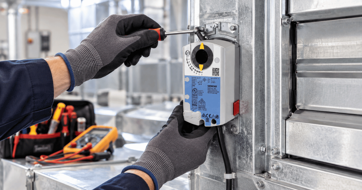
VAV Box Explained: How Variable Air Volume Systems Control Airflow
 October 1, 2026