
What Our Customers Are Saying
How to Wire a Valve Actuator to a BMS
12
Jun
How to Wire a Valve Actuator to a BMS
Signal Types: Choosing the Right Actuator for Your BMS Output
Before running any cable, confirm what type of output the BMS controller or FCU controller is providing. UK commercial BMS controllers typically provide one of three types of output to valve actuators: 0–10V analogue modulating, 2–10V analogue modulating (common on Carel pCO controllers), or 3-point floating (Y1/Y2 digital open/close pulse outputs). These are not interchangeable, ordering the wrong actuator type is the most common actuator commissioning mistake on UK HVAC projects.
For a full foundational overview of HVAC control strategy, see the HVAC Controls Practical Guide.
For Carel pCO and pCOe controllers driving FCU heating and cooling valves, the analogue output is typically 0–10V or 2–10V depending on how the pCO is configured. Check the pCO application software documentation for the output type before specifying actuators. Most Belimo NM, LM and SM series actuators accept 0–10V and 2–10V on the same Y input terminal.
Belimo NM24A-SR: Wiring for 0–10V BMS Analogue Output
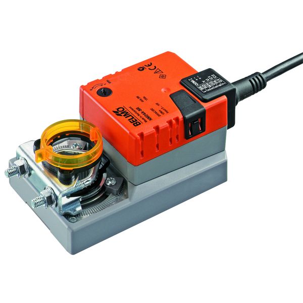
The NM24A-SR is a standard (non-spring-return) rotary actuator for Belimo B-series characterised ball valves, DN10–DN15. 10 Nm torque, 24V AC/DC supply, 0–10V modulating input, 90-second run time, IP54.
Terminal G: 24V supply positive (AC or DC). Terminal G0: 24V supply neutral/negative. Terminal Y: 0–10V signal from BMS analogue output. The actuator drives to full open at 10V and spring-returns to closed at 0V or on power loss.
Position feedback: if the BMS requires position feedback, wire terminal U to a BMS analogue input. The U terminal outputs 2–10V proportional to actuator position, 2V = closed, 10V = fully open. Use this to confirm the actuator is reaching full stroke from the BMS rather than visiting site.
✓ Always wire from a single 24V transformer per circuit zone. Mixing actuators from multiple transformer circuits on the same G0 reference causes ground loops and can result in erratic actuator behaviour that is very difficult to diagnose.
Belimo LM24A-SR: Wiring for FCU Applications
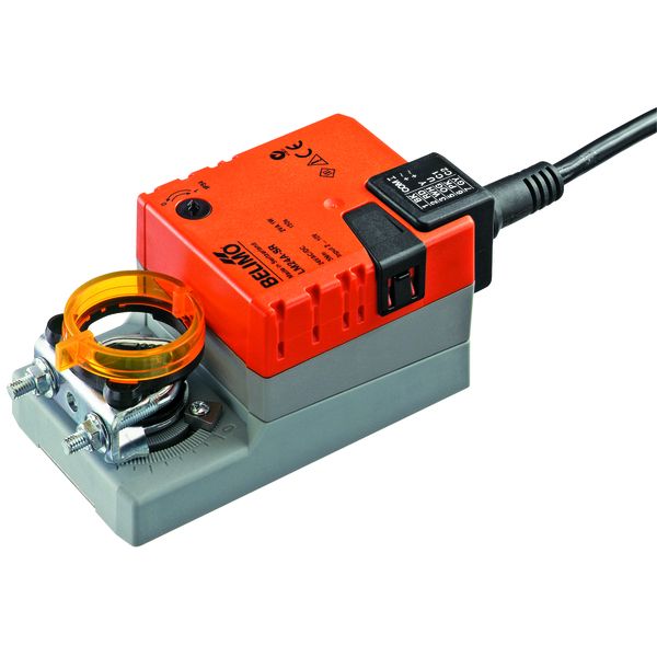
The LM24A-SR is a standard (non-spring-return) rotary actuator for Belimo B-series CBVs (DN15–DN25). 5 Nm torque, 24V AC/DC, 0–10V input, 150-second run time.
Wiring is identical to the NM24A-SR: G (24V+), G0 (neutral), Y (0–10V signal), U (2–10V position feedback).
Belimo SM24A-SR: Wiring for AHU Globe Valve Applications
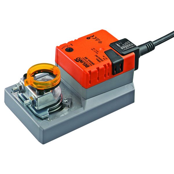
The SM24A-SR is a rotary actuator for larger Belimo B-series CBVs (DN25–DN50) and for Danfoss AB-QM PICVs via M30 adapter. 20 Nm, 24V AC/DC, 0–10V input, spring return, 150-second run time.
Wiring is identical to the NM24A-SR: G (24V+), G0 (neutral), Y (0–10V signal), U (2–10V position feedback). The longer run time on the SM24A-SR matters for AB-QM installations, the 150-second stroke time reduces water hammer risk on larger valves.
Siemens SAS61.33: Wiring for 0–10V BMS Analogue Output (Spring Return)
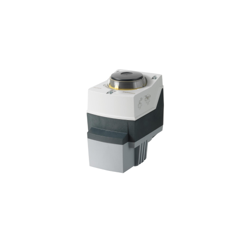
The SAS61.33 is the linear spring-return electromotoric actuator for Siemens VVF53 globe valves (DN15–DN32), 5.5 mm stroke, 24V AC, 0–10V modulating. Do not confuse with the SAS61.03 (0–10V modulating, non-spring-return) or SAS81.03/SAS31.03 (3-point floating).
Terminal G: 24V AC supply. Terminal G0: neutral. Terminal Y1: 0–10V analogue signal from BMS. Valve closes at 0V, fully opens at 10V. Spring return to closed on power loss.
For 3-point floating control (SAS81.03 or SAS31.03): Terminal Y1 receives the open pulse from the BMS digital output. Terminal Y2 receives the close pulse. The BMS pulses Y1 to open the valve and Y2 to close it. No proportional control, the Siemens actuator runs at full speed until the BMS stops the pulse, or until end stops.
⚠️Do not connect a continuous 10V signal to the Y1 terminal of an SAS81.03 or SAS31.03. It will drive to fully open and stay there regardless of demand. These 3-point actuators require momentary pulse signals, not a continuous analogue voltage.
Danfoss AME 110NL: Wiring for AB-QM PICV
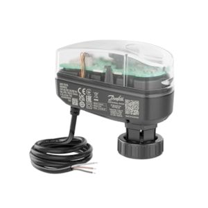
The AME 110NL is the correct linear modulating actuator for the Danfoss AB-QM PICV (DN15–DN32). Linear, M30 × 1.5 direct thread, 0–10V, spring return to closed, 24V AC/DC. (The AMB182 is a rotary actuator and is not physically compatible with the AB-QM PICV.)
Terminal 1 (G): 24V supply. Terminal 2 (G0): neutral. Terminal 3 (Y): 0–10V signal. Terminal 4 (U): 2–10V position feedback to BMS (optional). The AME 110NL drives to the stroke position corresponding to the input voltage and spring-returns to closed on power loss or 0V signal.
Cable Specification for Actuator Wiring
Signal cables to valve actuators must be screened twisted pair, unscreened cable in containment shared with power conductors will introduce noise on 0–10V signal cables, causing Belimo actuator hunting or random movement. Use 0.5 mm² or 0.75 mm² screened twisted pair for signal runs up to 100 m. Earth the screen at the BMS panel end only, earthing at both ends creates a ground loop that introduces the noise you are trying to screen out. Use separate containment for signal cables and power cables on all runs over 5 m.
Common Wiring Errors and How to Diagnose Them
|
Symptom |
Likely cause |
Test |
Fix |
|---|---|---|---|
|
Actuator doesn't move at all |
No 24V supply at actuator |
Measure G to G0, should read 24V AC or DC |
Check MCB, transformer, and cabling from panel to actuator |
|
Actuator goes fully open or closed only, no modulation |
0–10V BMS output connected to 3-point (SAS81.03/SAS31.03) actuator |
Check actuator model number |
Replace with SAS61.33 or equivalent 0–10V modulating spring-return actuator |
|
Actuator hunts / moves randomly without BMS signal change |
Signal cable noise |
Measure Y to G0 on a static BMS output, should be stable ±0.05V |
Use screened cable, earth screen at panel end only |
|
Zone always too hot or too cold, actuator at 0% or 100% |
Position feedback (U terminal) wired to wrong BMS input, false closed loop |
Check BMS trend: is actuator output always at limit? |
Verify U terminal wiring and BMS input channel assignment |
|
Actuator moves but valve doesn't |
Coupling/adapter disengaged |
Try manual override at actuator, if valve doesn't move, coupling is disengaged |
Re-engage coupling; check thread engagement (M30 for AB-QM, direct couple for SAS/SAX) |
Frequently Asked Questions
Q: Can I run multiple actuators from one 24V transformer?
Yes, but size the transformer for the combined inrush load. Allow 6–8 VA per actuator for running load and size the transformer at 1.5× calculated running load. Using undersized transformers is the most common cause of intermittent actuator failures on multi-FCU circuits.
Q: What does the U terminal on a Belimo actuator do?
It provides a 2–10V position feedback signal proportional to actuator stroke, 2V = fully closed, 10V = fully open. Wire this to a BMS analogue input if you need to confirm actual valve position from the BMS or trend valve stroke over time.
Q: What cable should I use for 0–10V actuator signal runs?
Screened twisted pair, 0.5 mm² or 0.75 mm², installed in separate containment from power cables. Screen earthed at BMS panel end only.
Comment(s)
Recent Posts
-
Steam Humidifier Explained: How HygroMatik Humidification Systems Work
 October 16, 2026
 -
Carel Controller Fault Codes Explained: A Troubleshooting Guide
 October 15, 2026
 -
Damper Actuator Not Working? How to Diagnose and Fix Common Faults
 October 2, 2026
 -
VAV Box Explained: How Variable Air Volume Systems Control Airflow
 October 1, 2026
 -
Replacing a CAREL pLDPRO Display: pGDn Options, Fit Checks and Affected Part Numbers
 September 23, 2026