
What Our Customers Are Saying
HVAC Controls: The Practical Engineer's Guide
8
Jun
Who This Guide Is For
This guide is written for Mechanical and Electrical Engineers, commissioning engineers, and site engineers working on UK commercial HVAC systems. It assumes you know what a BMS is, what a VSD does, and the difference between LTHW and chilled water. It does not explain what HVAC stands for. What it does is answer the questions that come up on site — which actuator wires go where, what the FC102 PID parameters should be set to first, why the Belimo isn't reaching full stroke, and how to commission a PICV system so you sign it off correctly and it stays working.
All products referenced are stocked at iACS and available for UK next-day delivery. Part numbers are given throughout.
The HVAC Controls Stack: How the Components Fit Together
Before getting into individual how-to guides, it helps to understand where each component sits in the control chain. A typical commercial HVAC zone, an FCU-served open-plan office, for example, has the following control hierarchy:
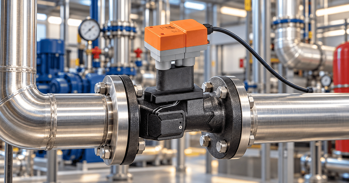
The BMS (or standalone FCU controller) calculates the required output based on zone temperature versus setpoint. It outputs a 0–10V analogue signal (or 3-point floating signal) to a valve actuator. The actuator positions the control valve to modulate water flow through the FCU heating or cooling coil. The coil transfers heat to or from the air, and the zone temperature changes. The room temperature sensor feeds back to the controller, and the loop continues.
Alongside this, a variable speed drive (VSD) on the distribution pump maintains system differential pressure as terminal valves open and close. Sensors throughout the system, duct pressure, water temperature, humidity, feed data back to the BMS for monitoring, trend logging, and plant-level control.
The control chain has five layers: sensors feed the controller, the controller signals the actuator, the actuator positions the valve, the valve modulates flow, and the VSD adjusts pump speed to match. A problem at any layer can present as a temperature control failure. Effective fault-finding means identifying which layer the problem is actually in before touching anything.
Commissioning a Variable Flow HVAC System: The Right Sequence
Variable flow HVAC systems, 2-port control valves, PICV terminals, VSD pump, must be commissioned in the right sequence. Doing it out of order is the single biggest cause of commissioning failures that take weeks to trace. The correct sequence is: mechanical completion first, then hydraulics, then electrical and BMS, then control loop tuning.
Mechanical completion means all pipework is complete, all valves are installed in the correct flow direction, all strainers are clean, and the system is filled, vented and pressure-tested. Hydraulic commissioning cannot begin on an air-locked or partially filled system. The symptoms of an air lock, low flow, unstable flow readings, and terminal under-heating are identical to several other faults and lead engineers to chase the wrong cause.
For PICV systems (Danfoss AB-QM), set the flow limiter rings to design flow on every terminal before system fill; these are your commissioning balancing values, and unlike traditional manual balancing valves they are set off the pressure of the system, not iteratively against it. Record every setting. Fill and vent. Start the distribution pump and measure differential pressure at the index (most remote) terminal. Confirm it exceeds 15 kPa at design conditions. Above this threshold, all AB-QM terminals are self-regulating.
Electrical and BMS commissioning follows once hydraulics are proven. Wire actuators, confirm 24V supply at each actuator, check signal types match (0–10V analogue to 0–10V actuators; 3-point floating to 3-point actuators, they are not interchangeable). Commission BMS control loops starting with the most accessible zones. Tune PID parameters starting from conservative values, a wide proportional band and long integration time, and tighten gradually.
Wiring Valve Actuators: The Essentials
The majority of valve actuator wiring faults on UK commercial HVAC projects fall into three categories: signal type mismatch, supply voltage issues, and incorrect spring return specification. Understanding each one prevents the most common callbacks.
Signal Type Mismatch
Belimo and Siemens actuators come in both 0–10V analogue modulating and 3-point floating control variants. These look similar in the catalogue and are often installed interchangeably by mistake. A 3-point actuator connected to a 0–10V BMS analogue output will not respond at all, it requires pulsed open/close digital signals. A 0–10V actuator connected to a 3-point output will move to full open or full closed only, with no modulation.
Belimo NM24A-SR and LM24A-SR are standard (non-spring-return) rotary actuators. The NM24A-SR for smaller FCU and AHU coil CBV applications, the LM24A-SR for larger CBVs. Siemens SAS61.33 is the 0–10V modulating spring-return variant for VVF53 globe valves; SAS81.03 or SAS31.03 are the correct 3-point floating variants. Check the model number on the label before ordering or installing.
24V Supply and Transformer Sizing
Most commercial HVAC actuators run on 24V AC or DC. A single zone transformer typically serves multiple actuators, the combined inrush current when all actuators start simultaneously is significantly higher than the steady-state running current, and undersized transformers trip or run hot. As a rule of thumb, allow 6–8 VA per actuator for the running load and size the transformer for 1.5× the calculated running load to accommodate inrush.
Measure supply voltage at the actuator terminals (G and G0 on Belimo, G and G0 on Siemens) as the first step in any actuator fault-finding sequence. No supply at the actuator means the fault is upstream of the actuator entirely.
Spring Return: Fail-Safe Specification
Spring return actuators store mechanical energy to guarantee a defined valve position on power failure, independent of all electrical systems. For LTHW heating coil valves, specify spring return to closed (valve closes on power loss, preventing uncontrolled heating). For chilled water cooling coil valves serving critical spaces (server rooms, occupied offices), specify spring return to open (valve opens on power loss, maintaining cooling). For general AHU cooling coil valves on systems with standby power, spring return to last position may be acceptable, but this is a project-specific decision that must be documented in the O&M manual.
⚠️Specifying spring return to the wrong fail position is a life safety issue on certain applications, server room cooling, operating theatre pressurisation, critical process temperature control. Confirm fail position explicitly with the design engineer before ordering.
The Danfoss FC102: Setting Up PID for VAV and Variable Flow
The FC102 HVAC variable speed drive is the dominant dedicated HVAC VSD in UK commercial buildings. Its built-in PID controller, which can accept process variable feedback directly from duct pressure, water DP, or temperature sensors, eliminates the need for a separate external controller on most HVAC pump and fan applications.
For a VAV supply fan application, connect a duct static pressure transducer (0–10V output, 0–1,000 Pa range) to analogue input AI53 or AI54. Set parameter 20-14 (reference/feedback source) to the AI input, parameter 20-21 (setpoint) to the target duct static pressure, and enable the internal PID. Start with P gain 0.5 (parameter 20-93) and integration time 20 seconds (parameter 20-94). Commission by confirming the fan responds smoothly to VAV damper openings and closings and settles at setpoint without hunting.
For variable flow pump control, the feedback signal is typically a remote differential pressure transmitter at the index circuit location. The FC102 maintains constant DP as terminal valves open and close. Start with the same conservative PID values. If the system hunts, increase integration time before increasing P gain.
Fault-Finding HVAC Controls: A Systematic Approach
The most effective fault-finding approach on HVAC controls is to work systematically from the sensor or setpoint through the control chain to the final element, ruling out each layer before moving to the next. A temperature complaint in a zone could have its root cause at any of: a faulty room temperature sensor reading incorrectly, a BMS setpoint that has been changed, a signal cable fault between BMS and actuator, an actuator that has lost power or is mechanically failed, a valve that is stuck or incorrectly sized, or a hydraulic issue that means correct valve operation still doesn't deliver the design flow.
On site, the fastest diagnostic path is: check the BMS trend data first (what has the zone temperature and actuator output been doing over the last 24–48 hours?), then check voltage at the actuator, then check valve position manually, then check flow and DP at the terminal.
Belimo Actuator Not Responding
Check 24V supply at G and G0 first. If supply is present, measure the control signal at Y and G0. For 0–10V actuators: 0V = fully closed, 10V = fully open. If the signal is correct but the actuator doesn't move, try the manual override. If the valve moves manually but not on signal, the actuator is faulty. If the valve doesn't move manually either, the valve is stuck or seized. Confirm the actuator is the correct model for the valve connection: Belimo B-series (CBV) requires a rotary actuator; globe valves require a linear actuator. Fitting a rotary actuator to a globe valve is a common error.
Siemens SAS61 / SAX61 Not Responding
Confirm model number before anything else: SAS61.03 is 0–10V modulating (non-spring-return), SAS61.33 is 0–10V modulating spring-return. For 3-point floating control, use SAS81.03 or SAS31.03. They are wired differently and will not respond to the wrong signal type. Check 24V at G and G0. On the SAS61.33, measure 0–10V at Y1 and G0, signal present but no movement means a mechanical fault or coupling issue. The SAS61.33 uses a direct-coupled connection to the Siemens VVF/VXF valve spindle; confirm the coupling is correctly engaged before assuming actuator failure.
Carel pCO Controllers: Key Setup Points
The Carel pCO range (pCO1, pCO3, pCO5, pCOe) is the most widely used parametric and programmable HVAC controller in UK commercial HVAC. It is used in AHU applications, chiller plant control, and fan coil unit multiplexed installations. The pCO system uses a proprietary RS485 bus (pLAN) to network controllers, I/O expansion modules, and graphic terminals, understanding the address structure and bus termination rules is essential before commissioning.
The most common setup issues on a Carel pCO installation are: incorrect analogue input type configuration (voltage vs current vs passive, set in the firmware parameters and matched to the physical DIP switch positions on older units), incorrect pLAN address assignment causing bus conflicts, and missing or incorrectly placed RS485 bus termination resistors producing intermittent communications errors.
HVAC Sensor Selection and Wiring
Sensors are the most frequently overlooked component in HVAC controls design, and sensor problems are responsible for a disproportionate share of ongoing operational complaints once systems are commissioned. The most common sensor issues are: wrong sensor type for the signal input (PT1000 connected to a NTC input, for example), incorrect placement causing the sensor to read an unrepresentative value, and cable shielding problems on long runs causing noise on 4–20 mA or 0–10V outputs.
For room temperature sensors on fan coil applications, position the sensor in the return air stream, not on the ceiling directly above the unit where stratification affects the reading, and not adjacent to a supply air diffuser. For duct temperature sensors, ensure a minimum of 10 duct diameters of straight duct upstream to achieve representative mixing. For water temperature sensors, immersion sensors must be installed in sensor pockets in the correct orientation and with adequate thermal contact compound.
Product Reference: Key Parts Stocked at iACS
|
Product |
Description |
Common application |
|---|---|---|
|
Rotary, 0–10V, non-spring-return (standard), 10 Nm, 24V |
FCU CBV DN10–DN15 |
|
|
Rotary, 0–10V, non-spring-return (standard), 5 Nm, 24V |
FCU CBV DN15–DN25 |
|
|
Rotary, 0–10V, spring return, 20 Nm, 24V |
AHU CBV DN25–DN50 |
|
|
Linear, 0–10V, spring return, 5.5 mm, 24V |
VVF53 globe valve |
|
|
Linear, 0–10V, spring return, 20 mm, 24V |
VXG44 globe valve |
|
|
Linear, 0–10V, spring return, M30×1.5, 24V, correct actuator for AB-QM PICV |
AB-QM PICV all DN |
|
|
PICV, 40–540 l/h, DP 15–400 kPa |
FCU small terminals |
|
|
PICV, 100–1050 l/h, DP 15–400 kPa |
FCU medium terminals |
|
|
HVAC VSD, 0.37–90 kW, BACnet/Modbus |
AHU/pump variable speed |
|
|
Programmable HVAC controller, pLAN/BACnet |
AHU control |
|
|
Duct temperature sensor, PT1000 |
AHU supply/return temp |
UK Standards Engineers Should Know
CIBSE Guide H covers BMS design and specification, the definitive UK reference for control system architecture, sensor specifications, and protocol selection. CIBSE KS18 covers variable flow systems and PICV application. CIBSE TM39 addresses building energy metering. BESA DW/TM2 is the commissioning standard for HVAC hydronic systems and contains the commissioning procedures for both traditional balancing and PICV-based systems. BS EN ISO 16484 covers the BACnet standard as implemented in UK building management systems. For VSD harmonic compliance, ER G5/5A is the UK Engineering Recommendation governing harmonic injection into the distribution network.
Frequently Asked Questions
Q: What is the difference between 0–10V and 3-point actuator wiring?
A 0–10V actuator receives a continuous analogue voltage signal (0V = closed, 10V = open) and positions proportionally. A 3-point actuator receives pulsed open or close digital signals and runs its motor until it reaches the commanded position. A 0–10V BMS output cannot drive a 3-point actuator, no movement will result.
Q: How do I know which Siemens actuator to order for a VVF53 valve?
The Siemens VVF53 has a 5.5 mm stroke. It requires the SAS61 series actuator. For 0–10V modulating BMS control with spring return, order SAS61.33. For 0–10V modulating without spring return, order SAS61.03. For 3-point floating control, order SAS81.03 or SAS31.03. The SAX61 series is for VXG44 valves (20 mm stroke) and will not fit the VVF53.
Q: Why is my variable flow system not balancing after commissioning?
Most likely cause: system DP at one or more terminals is below 15 kPa (for AB-QM PICVs), meaning the DP regulator is not activated. Check pump DP and strainer condition. Second most likely: one or more AB-QM flow setting rings are set incorrectly. Third: airlocks at high points are affecting flow distribution.
Q: Can I use a Belimo actuator on a Siemens valve?
Yes, Belimo actuators can be fitted to most Siemens globe valves using adapter kits. The Belimo LMB24-SR-S and SMB24A-SR fit Siemens VVF53 and VXG44 valves, respectively using Belimo's VZ yoke and adapter systems. Check the Belimo/Siemens compatibility table for the specific valve DN.
Q: What PID settings should I start with on the Danfoss FC102?
For duct static pressure VAV control: P gain 0.5, I time 20 s as starting values. For variable flow pump DP control: P gain 0.3, I time 30 s. Both are deliberately conservative, stable from the start, then tighten. Hunting from a standing start on a fresh commission means the gain is already too high.
Comment(s)
Recent Posts
-
How to Choose an HVAC Actuator: Torque, Voltage and Signal Type Explained
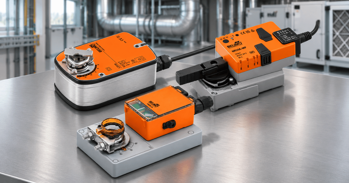 November 3, 2026
-
CO2 Sensors Explained: Demand Controlled Ventilation for Better Air Quality
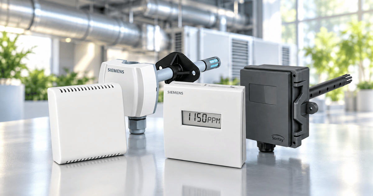 November 2, 2026
-
Humidity Sensors Explained: Types and Applications in HVAC
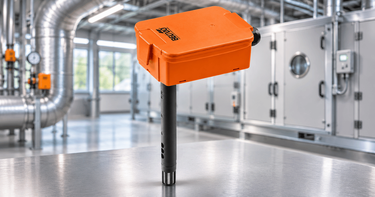 November 1, 2026
-
Immersion versus Strap On versus Duct Temperature Sensors: Which Should You Choose
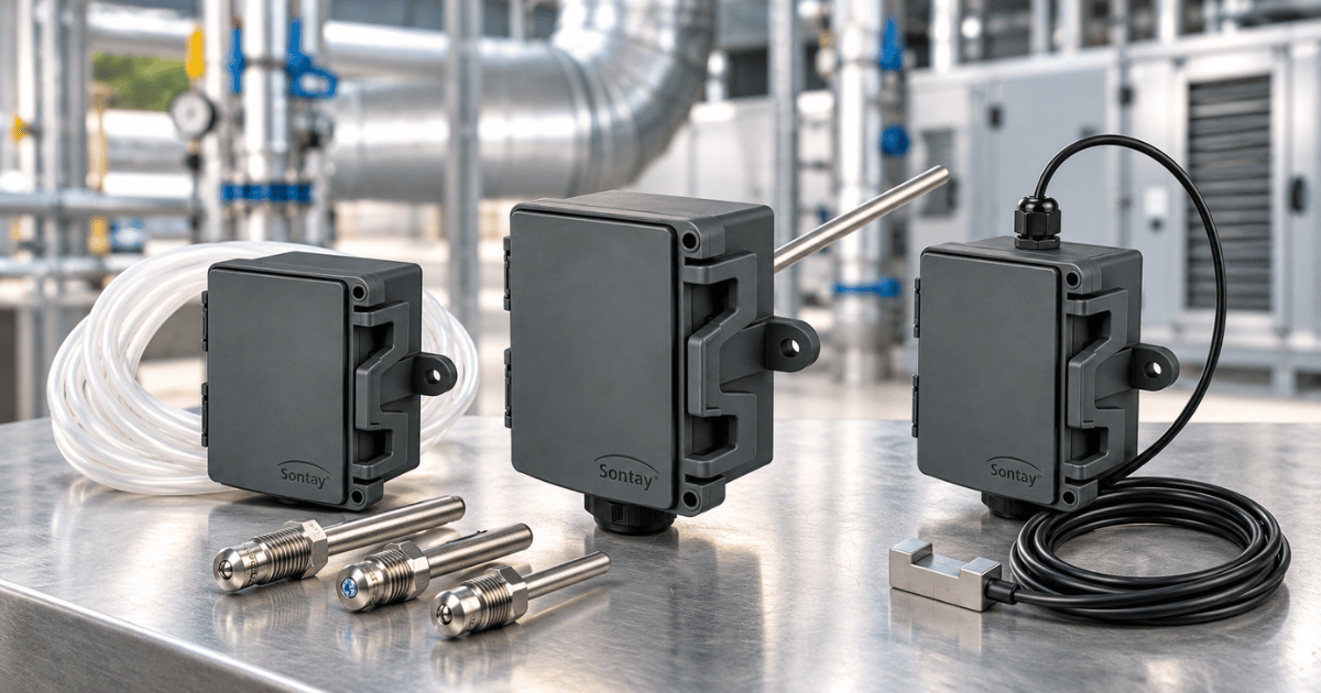 October 26, 2026
-
Water Flow Switch Explained: How It Works and Common Faults
 October 21, 2026