
What Our Customers Are Saying
Carel pCO Controller: Wiring and Setup Guide
22
Jul
The pCO Product Family: Which Unit for Which Application
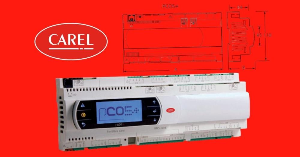
The pCO range covers a spectrum from small FCU multiplexing to large AHU and chiller applications. The pCO1 and pCOe are compact units for small AHU and FCU applications with limited I/O. The pCO3 is the standard mid-range unit for UK AHU controllers; it has sufficient universal analogue inputs (8 on pCO3), digital inputs, and relay outputs for most four-pipe AHU applications without expansion modules. The pCO5 and pCO5+ are the full-specification controllers for complex AHU and chiller plant, with up to 20 universal inputs and 12 relay outputs, expansion module support via pLAN, and BACnet IP/Ethernet communication as standard.
All pCO variants use the same firmware structure and the same pLAN RS485 bus for networking controllers, terminals and I/O expansion modules. The EPROM or microSD card contains the application software, AHU application, chiller application, or custom code written in Carel's PCOPROJ IDE. On-site, you are always configuring parameters within a specific application, not working with blank firmware.
For a full foundational overview of HVAC control strategy, see the HVAC Controls Practical Guide.
Analogue Input Configuration: The Most Common Commissioning Error
The pCO's universal analogue inputs accept multiple sensor types, NTC thermistors, PT1000 RTDs, 4–20 mA current signals, and 0–10V voltage signals, but only the type that the input is configured for in the application parameters AND physically wired for on the terminals. Getting these two things out of sync is the most common source of erroneous sensor readings on UK pCO installations.
For a PT1000 temperature sensor (duct temperature, water temperature): the sensor connects directly between the input terminal and the G0 (GND) terminal with no external supply required. In the application software, the input type parameter for that channel must be set to PT1000. If it is set to NTC, the controller will calculate a completely wrong temperature from the PT1000's resistance characteristic.
For a 4–20 mA pressure transmitter: wire the supply (typically 24V DC from the pCO's power supply) to the transmitter positive, the transmitter negative (current loop return) to the pCO analogue input terminal, and GND to G0. Set the input type to 4–20 mA in the application parameter. Do not try to power 4–20 mA transmitters from the pCO's 24V AC supply, use the DC supply terminal.
For a 0–10V humidity or CO2 sensor: wire 24V to the sensor supply, sensor output to the pCO analogue input, and GND to G0. Set input type to 0–10V. On older pCO3 units with hardware DIP switches, also set the DIP switch for that input channel to match the software configuration.
⚠ On pCO3 units with input DIP switches, software configuration and DIP switch position must both be correct. Software set to PT1000 but DIP switch in 0–10V position produces incorrect readings with no fault indication, one of the most time-consuming pCO faults to diagnose.
pLAN Bus: Address Assignment and Termination
The pLAN RS485 bus connects pCO controllers to each other, to I/O expansion modules, and to graphic terminals (pGD touchscreen or Carel pGDE). Each device on the pLAN bus has a unique address set via DIP switches on the device or via the terminal interface. Address conflicts, two devices with the same address, cause intermittent communication errors that can appear as random I/O dropout or false sensor values.
Set addresses sequentially from address 1. The pCO master controller is typically address 1. I/O expansion modules and terminals take subsequent addresses. Check for conflicts by monitoring the pLAN status indicators, a continuous fast blink on the pLAN LED indicates communication activity; no blink with other devices on the bus indicates a wiring fault or bus conflict.
RS485 bus termination: fit a 120 Ohm termination resistor at each physical end of the pLAN bus. On most pCO devices this is done via a DIP switch (SW termination), not a physical resistor. Failure to terminate the bus produces reflections on longer cable runs that cause intermittent communication errors, particularly when multiple devices are communicating simultaneously. Fit termination at the two physical ends of the bus only, not at intermediate nodes.
Relay Output Wiring: DOs and DON'Ts
The pCO's relay outputs are volt-free contacts rated for 8A at 250V AC or 24V. For fan speed relay outputs on AHU applications: wire the relay in series with the fan contactor coil circuit, with the relevant phase supply on the relay common terminal and the contactor coil on the relay normally open terminal. Do not connect high-voltage (400V) loads directly to pCO relay outputs, the relay is rated for 250V maximum. Use the pCO relay to drive a contactor coil only.
For valve actuator on/off control from a pCO relay output (rather than an analogue output): connect the relay common to 24V AC, the normally open contact to the actuator G terminal, and wire G0 between actuator and transformer neutral. This gives a simple switched 24V AC supply for on/off valve control.
Frequently Asked Questions
Q: My pCO is showing an incorrect temperature on a duct sensor, how do I fix it?
Check both the application parameter for input type AND the DIP switch setting on the hardware (pCO3 only). Both must be set to the correct sensor type. Confirm the sensor resistance at the controller terminals using a multimeter, a PT1000 reads approximately 1,085 Ohm at 22°C.
Q: The pLAN terminal is showing 'no connection'. What should I check?
Check RS485 cable polarity (A/B swap produces no communication), bus address conflicts, and termination resistor positions. Confirm the cable is twisted-pair screened, and the screen is earthed at one end only. Use the pCO's built-in pLAN diagnostics to identify which address is conflicting.
Q: Can the pCO5+ communicate directly with a Trend or Siemens BMS?
Yes, the pCO5+ has BACnet/IP and BACnet MS/TP as standard, which is supported by Trend IQ, Siemens DESIGO, and all major UK BMS platforms. Use the Carel supervisor setup parameters to configure BACnet device address, baud rate, and object list.
Comment(s)
Recent Posts
-
Steam Humidifier Explained: How HygroMatik Humidification Systems Work
 October 16, 2026
 -
Carel Controller Fault Codes Explained: A Troubleshooting Guide
 October 15, 2026
 -
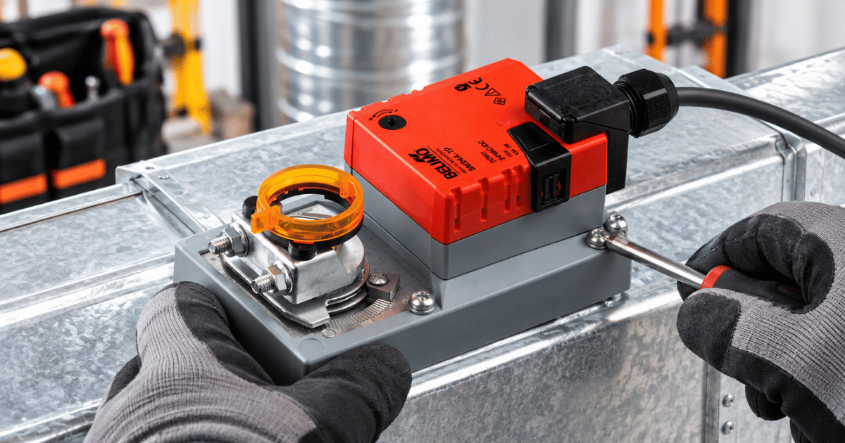
Damper Actuator Not Working? How to Diagnose and Fix Common Faults
 October 2, 2026
 -
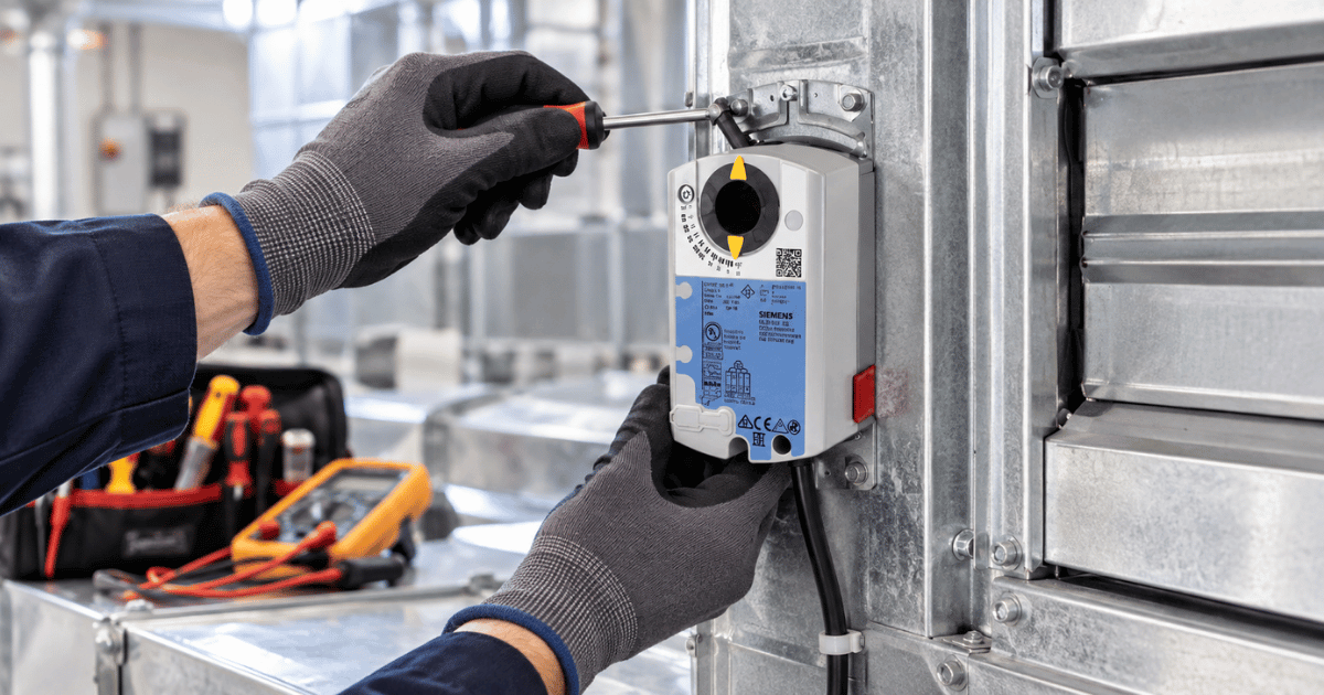
VAV Box Explained: How Variable Air Volume Systems Control Airflow
 October 1, 2026
 -
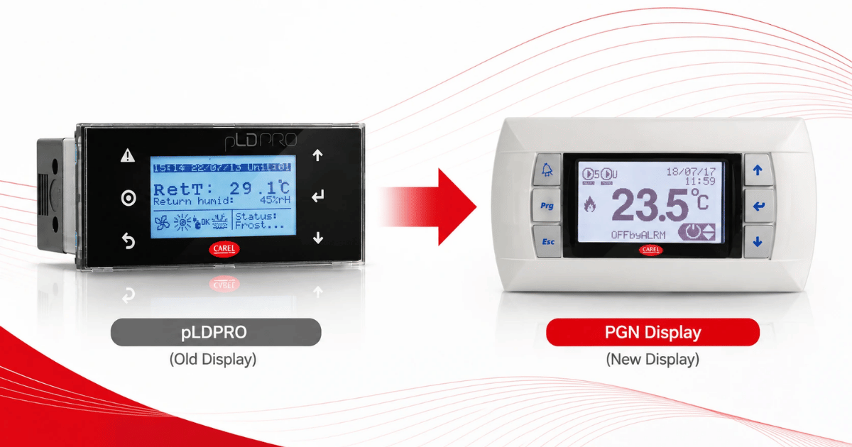
Replacing a CAREL pLDPRO Display: pGDn Options, Fit Checks and Affected Part Numbers
 September 23, 2026