
What Our Customers Are Saying
HVAC Sensor Selection and Wiring Guide
31
Jul
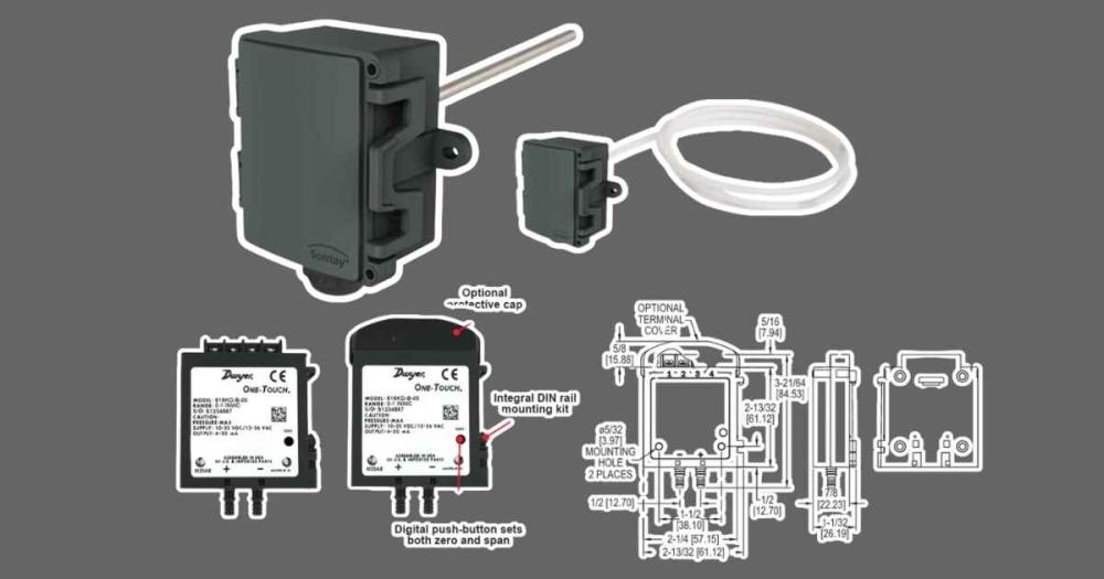
The Four Sensor Signal Types
Every HVAC sensor you'll encounter on a UK commercial project uses one of four signal types, and the controller input must be configured to match. Using the wrong configuration produces readings that are systematically wrong, not obviously wrong, but offset in a way that causes control problems without triggering any fault alarm.
- PT1000 (resistance): A resistive temperature sensor with 1,000 Ohm resistance at 0°C, increasing approximately 3.85 Ohm per degree Celsius. PT1000 is the standard for duct temperature, pipe temperature, and room temperature sensors on all Carel pCO and most BMS-connected HVAC applications in UK commercial buildings. Two-wire connection to BMS analogue input, passive, no supply required. Brands: Sontay RU series (duct), Sontay RO series (pipe pocket/surface), Sontay RS series (room).
- NTC (resistance): Negative temperature coefficient thermistor. High sensitivity at low temperatures, commonly used in residential and light commercial applications and as built-in sensors in FCU controllers. Not suitable for long cable runs (high impedance affects accuracy). Do not substitute an NTC for a PT1000 input, the resistance-temperature curves are completely different.
- 4–20 mA (current loop): Two-wire active loop. Used for pressure transmitters (duct static, water DP), humidity sensors, CO2 sensors, and variable flow measurement. Loop-powered from controller or external 24V DC supply. Immune to cable resistance effects, suitable for long cable runs up to 300 m. Most commercial pressure and environmental sensors use 4–20 mA.
- 0–10V (voltage): Active voltage output. Used for humidity sensors, CO2 sensors, combined temperature/humidity sensors, and some pressure transmitters. Requires external 24V supply to the sensor. More susceptible to cable noise than 4–20 mA on longer runs, use screened cable for runs over 20 m.
Duct Temperature Sensors: PT1000 Wiring and Placement
The Sontay RU-DUCT and Sontay TE-DUCT series are the most widely used duct temperature sensors on UK commercial AHU installations. Both use PT1000 elements. Wire the two sensor cores to the controller's PT1000 input terminals, no polarity, no supply. For cable runs over 30 m, use 0.5 mm² or larger cable to minimise resistance error (cable resistance adds to the apparent sensor resistance, causing a reading that is systematically low).
Placement matters as much as wiring. Position duct sensors a minimum of 10 duct diameters downstream of any mixing point, bend, or obstruction to ensure the air stream is well-mixed and the sensor reads a representative temperature. On supply air ductwork with a heating or cooling coil immediately upstream, the stratification immediately post-coil can cause a sensor to read 3–5°C higher or lower than the actual supply air temperature, a source of continuous hunting that appears to be a control problem.
Pipe Temperature Sensors: PT1000 Pocket Sensors
Immersion pocket sensors (Sontay RO series) fit into welded bosses in the pipework and measure water temperature directly. The sensor must be installed with a thermal contact compound in the pocket to ensure good heat transfer, without it, the sensor reads air temperature inside the pocket rather than water temperature, introducing a significant lag and error. Confirm pocket length matches the pipe bore, a pocket that doesn't reach the centre of the pipe on large bore applications reads the wall temperature, not the flow temperature.
For commissioning verification, confirm the pipe temperature reading against a clamp-on surface thermometer at the same location as a quick sanity check before commissioning a temperature control loop.
Differential Pressure Transmitters: 4–20 mA Wiring
The Sontay (duct) and Dwyer Series 616 (duct and pipe) are the most common DP transmitters on UK commercial HVAC. Both output 4–20 mA proportional to the pressure differential across the high and low pressure tappings.
Wire the transmitter supply (24V DC) to the positive terminal and the controller analogue input (configured for 4–20 mA) to the negative/signal terminal. The 4–20 mA current flows through the loop from supply, through the transmitter, back through the controller input, and back to the supply common. Use the controller's 24V DC supply output if available; otherwise use a separate 24V DC PSU.
On the controller, scale the 4–20 mA input to the transmitter's pressure range: 4 mA = minimum pressure (typically 0 Pa or 0 kPa), 20 mA = maximum pressure. For a 0–1,000 Pa duct pressure transmitter, 12 mA represents 500 Pa. Confirm this scaling by applying a known pressure (or measuring an existing system pressure independently) and checking the controller reading matches.
Room Temperature Sensors: Placement Rules
Room temperature sensors feeding FCU or zone controllers must be positioned to read representative room air temperature, not the microclimate immediately adjacent to the unit. Position sensors on internal walls at approximately 1.5 m height, away from supply air diffusers, windows, heat-generating equipment, and direct sunlight. In open-plan offices, avoid positioning sensors immediately above or below FCU units, the supply/return air mixing around the unit creates a temperature reading that bears little relationship to the occupied space temperature.
For FCU applications with Carel pCOe or standalone FCU controllers, the room temperature sensor is typically the controller's built-in NTC element. For BMS-connected zone control, a separate PT1000 room sensor wired back to the BMS controller is standard practice.
Frequently Asked Questions
Q: My PT1000 sensor is reading 5°C below actual temperature, what is wrong?
Two most likely causes: (1) controller input configured as NTC rather than PT1000, reconfigure to PT1000; (2) long cable run with significant cable resistance adding to apparent sensor resistance, measure cable resistance and apply offset in the controller, or replace with larger cable.
Q: How do I check a PT1000 sensor with a multimeter?
Measure resistance between the two sensor terminals with the sensor disconnected from the controller. At room temperature (~20°C) a healthy PT1000 reads approximately 1,077 Ohm. Open circuit = sensor broken. Very low resistance (close to 0) = short circuit in sensor or cable.
Q: Can I run PT1000 and 4–20 mA sensors in the same cable?
Not recommended, run PT1000 and current loop signals in separate screened cables to prevent the 24V loop current inducing noise on the low-level resistance signal. Separate containment is preferable but separate cables in the same trunking is acceptable if both are individually screened.
Comment(s)
Recent Posts
-
EC Fans versus AC Fans Explained: Which Is Right for Your HVAC System
 October 17, 2026
 -
Steam Humidifier Explained: How HygroMatik Humidification Systems Work
 October 16, 2026
 -
Carel Controller Fault Codes Explained: A Troubleshooting Guide
 October 15, 2026
 -
Damper Actuator Not Working? How to Diagnose and Fix Common Faults
 October 2, 2026
 -
VAV Box Explained: How Variable Air Volume Systems Control Airflow
 October 1, 2026