
What Our Customers Are Saying
How to Set Up the Danfoss FC102 PID for VAV and Variable Flow
22
Jun
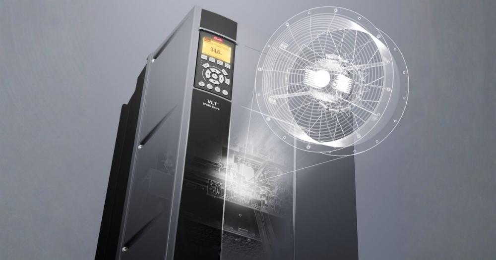
When to Use the FC102 Internal PID vs External BMS Control
The FC102's internal PID controller is appropriate for single-variable process control: one sensor, one drive, one setpoint. VAV supply fan duct static pressure is the classic application, the FC102 maintains a target duct static pressure setpoint by varying fan speed as VAV dampers open and close, with no BMS PID loop required. The same principle applies to variable flow pump DP control.
Use external BMS PID control when the control strategy involves multiple variables or complex sequencing that the drive's internal PID cannot handle, cascade heating sequences, reset strategies based on multiple zone demands, or AHU systems with economiser, heating, cooling, and humidification sequences. In these cases, the BMS handles the logic and provides a speed reference to the FC102 via BACnet or 0–10V analogue.
For a full foundational overview of HVAC control strategy, see the HVAC Controls Practical Guide.
Parameter Map: FC102 PID Setup
|
Parameter |
Function |
VAV duct pressure |
Variable flow pump |
|---|---|---|---|
|
1-20 |
Motor power (kW) |
Set to motor nameplate kW |
Set to motor nameplate kW |
|
1-22 |
Motor voltage |
Set to motor nameplate V |
Set to motor nameplate V |
|
1-23 |
Motor frequency |
50 Hz (UK) |
50 Hz (UK) |
|
1-24 |
Motor current |
Set to motor nameplate A |
Set to motor nameplate A |
|
20-00 |
Closed loop / open loop |
[1] Closed loop |
[1] Closed loop |
|
20-14 |
Feedback source 1 |
AI53 or AI54 (sensor input) |
AI53 or AI54 |
|
20-21 |
Setpoint 1 |
Target duct static pressure (Pa) |
Target DP (kPa or bar) |
|
20-70 |
PID, normal/inverse acting |
[0] Normal (more speed = more pressure) |
[0] Normal |
|
20-93 |
PID proportional gain |
0.5 (start) |
0.3 (start) |
|
20-94 |
PID integration time (s) |
20 s (start) |
30 s (start) |
|
20-95 |
PID differentiation time (s) |
0 (off, do not use) |
0 (off) |
|
3-02 |
Minimum reference (speed) |
20 Hz minimum (prevents fan stall) |
25 Hz minimum |
|
3-03 |
Maximum reference (speed) |
50 Hz (or design maximum) |
50 Hz |
Commissioning Sequence: VAV Duct Pressure Control
Wire a duct static pressure transducer (0–10V output, 0–1,000 Pa range, 24V DC powered) to analogue input AI53 on the FC102. Common transducers used with the FC102 on UK VAV systems include the Sontay Duct Pressure Transmitter and the Dwyer Series 616D, both are stocked at iACS. Wire the transducer supply from the FC102's 24V output terminal (terminal 12 positive, 55 ground).
Set parameter 6-10 (terminal 53 low voltage) to 0V and parameter 6-11 (terminal 53 high voltage) to 10V. Set parameter 6-14 (terminal 53 low reference) to 0 and 6-15 (terminal 53 high reference) to 1000 (Pa). This maps the 0–10V sensor output to 0–1,000 Pa. Confirm the feedback reading in the FC102 drive LCP display matches a known reference pressure before enabling closed loop.
Set parameter 20-21 (setpoint) to the design duct static pressure, typically 150–300 Pa for a medium commercial VAV AHU. Enable closed loop (parameter 20-00 = 1). The drive will now run at whatever speed maintains the setpoint.
With all VAV dampers commanded fully open by the BMS, confirm the FC102 runs at near-full speed. Command all VAV dampers to minimum position, the FC102 should reduce speed to maintain the DP setpoint. If the system hunts (fan speed oscillates), increase the integration time (parameter 20-94). If the system is slow to respond, reduce integration time by 20% and check the proportional gain is at least 0.5.
Commissioning Sequence: Variable Flow Pump DP Control
For variable flow pump control, the process variable sensor is a remote differential pressure transmitter installed at the index circuit, the most remote hydraulic point on the distribution system, where DP will be lowest at design flow. The Sontay PT-100 series and Dwyer Series 616 differential pressure transmitters are suitable for this application.
The wiring and parameter setup mirrors the VAV application: sensor to AI53 or AI54, scale parameters 6-10/6-11 and 6-14/6-15 to match the transmitter output and pressure range. Set the setpoint (parameter 20-21) to maintain 20–25 kPa at the index terminal, sufficient margin above the AB-QM 15 kPa activation threshold. Starting PID values: P gain 0.3, I time 30 s.
Verify correct pump rotation before enabling closed loop. Commission with all terminal valves commanded to design flow (actuators at full demand). Confirm DP at the index terminal reads above 15 kPa. Apply 0% demand to all terminals simultaneously and confirm the pump reduces speed, VSD energy savings are only being realised if the pump speed actually falls under reduced load.
Fire Mode Setup and Test
The FC102 fire mode function forces the drive to maximum speed on receipt of a digital input signal, overriding all BMS commands. Configure the digital input for fire mode using parameter 5-10 to 5-16 (terminal 18 to 33 as appropriate). Set the selected terminal to function [72] (fire mode). Test during commissioning by applying a voltage to the fire mode input and confirming maximum speed is reached and held regardless of any BMS speed reference. Document the test result.
⚠ Fire mode must be physically tested during commissioning, not just confirmed in the parameter settings. The test result must be recorded in the commissioning documentation and O&M manual.
Frequently Asked Questions
Q: The FC102 PID is hunting. How do I fix it?
Increase the integration time (parameter 20-94). On a VAV system, go from 20 s to 40 s. If still hunting, check the sensor is reading correctly and not spiking. Differential (parameter 20-95) should be 0, activating derivative on HVAC control applications almost always makes hunting worse.
Q: Can I set up the FC102 from the BMS instead of the drive keypad?
Yes, via BACnet MS/TP or Modbus RTU once communication is configured. But always set motor nameplate parameters (1-20 to 1-24) at the drive keypad on first commissioning, getting these wrong is the most common cause of motor thermal trips.
Q: How do I check what the FC102 is measuring from its sensor?
Use the FC102 LCP (keypad) to navigate to the status display and view the feedback process value. This shows the live sensor reading in engineering units as the drive sees it. If this value is wrong, the problem is in the sensor wiring or parameter scaling, not the PID.
Comment(s)
Recent Posts
-
Steam Humidifier Explained: How HygroMatik Humidification Systems Work
 October 16, 2026
 -
Carel Controller Fault Codes Explained: A Troubleshooting Guide
 October 15, 2026
 -
Damper Actuator Not Working? How to Diagnose and Fix Common Faults
 October 2, 2026
 -
VAV Box Explained: How Variable Air Volume Systems Control Airflow
 October 1, 2026
 -
Replacing a CAREL pLDPRO Display: pGDn Options, Fit Checks and Affected Part Numbers
 September 23, 2026