
What Our Customers Are Saying
Air Handling Units Explained: Controls, Components and Commissioning
20
Apr
An air handling unit (AHU) is the central hub of a mechanical ventilation system — the piece of equipment that conditions and distributes air throughout a building. Understanding how AHU controls work is fundamental for anyone specifying, installing, or commissioning HVAC systems.
This guide covers the anatomy of a typical AHU, the control components used at each stage, sensor placement, actuator and drive selection, and the commissioning steps that ensure the system operates as designed. For a wider overview of the full control architecture, see The Complete Guide to HVAC Controls.
What Is an AHU Air Handling Unit?
An AHU system is a packaged piece of mechanical equipment that treats supply air — typically drawing in outside air, mixing it with recirculated air, filtering it, heating or cooling it, humidifying or dehumidifying it, and delivering it to occupied spaces via a ductwork distribution system. Extract air is collected from occupied spaces and either recirculated, exhausted to atmosphere, or passed through a heat recovery section before exhaust.
Air handling units (AHUs) range from small rooftop units serving a single floor to large central plant room units serving entire buildings. The control complexity scales accordingly — a rooftop unit might run from a simple parametric controller, while a large central AHU typically integrates with a full BMS via BACnet or Modbus.
AHU Components and Their Controls
Fresh Air and Return Air Dampers
Motorised dampers control the proportion of fresh outside air and recirculated return air entering the mixing chamber. In a typical arrangement, the fresh air damper and return air damper are linked so that opening one closes the other. During an economiser mode (free cooling), the fresh air damper opens fully to take advantage of cool outside air.
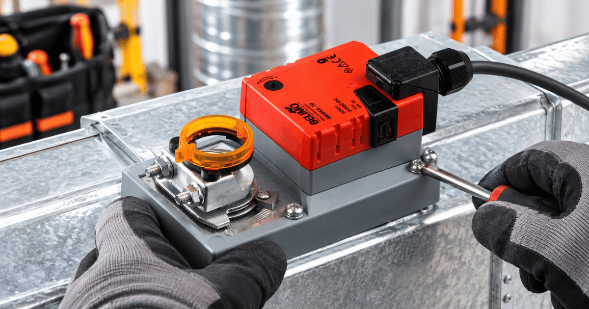
Damper actuators are selected based on the damper area and the torque required to operate the blades. Spring-return actuators are specified where fail-safe closure (or opening) is required — for example, a fresh air damper that must close if the fan fails, to prevent freezing of downstream coils in cold weather. For a deeper comparison of actuator types, see Damper Actuators: Spring Return vs Non‑Spring Return.
Filtration
Supply air passes through filters — typically a coarse G4 pre‑filter and a fine F7 or F9 bag filter. As filters load with particulate, the pressure drop across them increases, and this is where a differential pressure gauges becomes essential. Instruments such as Magnehelic‑type gauges provide a clear indication of rising pressure drop; if you’re unfamiliar with how these devices work, our guide to differential pressure gauges explains the different Magnehelic types and how they’re applied in HVAC systems.
A differential pressure sensor (or switch) monitors this pressure drop and triggers an alarm when filter replacement is due, ensuring the AHU maintains airflow and efficiency. For product options suitable for filter monitoring, you can browse our full range of pressure gauges.
Heating and Cooling Coils
Hot water or chilled water coils condition the supply air temperature. A modulating control valve regulates flow through the coil in response to the controller’s output signal — typically 0–10V or 4–20mA proportional output, or 3‑point floating control. Selecting the correct valve type is essential for stable temperature control; if you need a deeper comparison of valve characteristics and applications, our guide to selecting the right HVAC control valve covers this in detail.
For variable‑flow systems, pressure independent control valve (PICVs) eliminate the need for separate differential pressure control and simplify commissioning significantly. To understand how PICVs maintain consistent flow and why they’re now standard in modern HVAC design, see Pressure Independent Control Valves (PICVs) Explained.
Supply and Extract Fans
AHU fans are typically controlled by Danfoss variable speed drives (VSDs/inverters) to maintain a constant duct static pressure setpoint. As VAV terminal units in the zone open and close, the duct pressure changes, and the VSD adjusts fan speed to compensate — one of the most significant energy‑saving measures in a modern HVAC system. If you’re evaluating which drive is appropriate for your application, our guide on how to select a variable speed drive for HVAC breaks down the key considerations, from control modes to motor compatibility.
The Danfoss FC102 is purpose‑built for HVAC fan applications, with built‑in BACnet IP and Modbus TCP communication, an integrated bypass contactor option, and application‑specific logic for supply and extract fans. For available models suitable for AHU supply and extract fans, you can browse our full range of inverters and drives.
Humidification Section
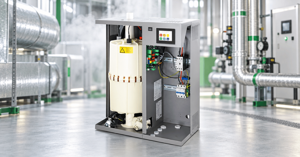
Where supply air humidity must be controlled — typically in spaces with precise comfort or process requirements — a humidifier section adds moisture to the supply air. Steam humidifiers (electrode or electric resistance) are the most common type for commercial HVAC, providing precise, hygienic humidification, while ultrasonic humidifiers are used in applications where lower water temperatures are acceptable. If you need a deeper comparison of these technologies and where each is best applied, our guide to humidification in HVAC — steam vs ultrasonic vs adiabatic breaks down the key differences.
The humidifier is controlled by an RH sensor in the supply duct or the occupied space, with the controller modulating output to maintain the setpoint. Separate RH high‑limit sensors in the supply duct protect against condensation downstream.
Heat Recovery
Heat recovery devices — rotary heat wheels, plate heat exchangers, or run-around coils — recover energy from exhaust air and transfer it to incoming fresh air. They dramatically reduce the energy needed to condition fresh air and are required by Part L of the Building Regulations in many new-build applications. Controls monitor the leaving temperatures and may bypass the heat recovery section if outside conditions make it counterproductive.
Sensor Placement in AHU Control
Correct sensor placement is critical — a correctly specified sensor in the wrong location will give misleading readings and cause control problems. Our engineer’s guide to HVAC sensors and measurement expands on these principles in detail, but the key placement rules for AHUs include:
- Supply air temperature sensor — positioned downstream of the heating/cooling coil, after any mixing, typically 1–2m downstream of the coil to allow temperature equalisation across the duct cross-section.
- Return air temperature sensor — positioned in the main return duct, away from the extract grille to avoid short-circuit readings from a single zone.
- RH sensor for humidifier control — in the supply duct, downstream of the humidifier and any duct mixing length (minimum 10 duct diameters downstream of the humidifier distribution grid).
- Differential pressure sensor for filter monitoring — tapped either side of the filter bank, static pressure sensing points ideally positioned at the face of the filter.
- Duct static pressure sensor — positioned in the main supply duct at approximately two-thirds of the duct length from the fan, away from elbows and transitions.
AHU Control Sequence — Typical Operation
- On the scheduled start signal (from the HVAC BMS or time clock), the extract fan starts at minimum speed.
- After proving airflow (the air differential pressure switch confirms the fan is running), the supply fan starts.
- Fresh air damper opens to the minimum fresh air position; return air damper adjusts accordingly.
- Supply air room temperature controller enables heating or cooling as required to reach the supply air temperature setpoint.
- Duct static pressure controller adjusts fan speed controller via an ABB VSD to maintain the setpoint as VAV boxes modulate.
- Humidity controller enables how a humidifier works if the supply air RH is below the setpoint.
- Heat recovery bypass controls based on outside and return air temperature comparison.
- On scheduled stop, fans ramp down, dampers close, frost protection strategy engages if outside temperature is near freezing.
For a broader context on how this sequence fits into the wider control architecture, you can return to The Complete Guide to HVAC Controls.
Commissioning AHU Controls: Key Steps
- Verify all sensor calibrations against a reference instrument before commissioning.
- Confirm correct communication addresses for all networked devices (BACnet instance numbers or Modbus slave IDs).
— If you’re comparing protocols, our BACnet vs Modbus guide outlines the key differences for HVAC applications
- Test all actuator end positions — fully open and fully closed — and confirm correct rotation and stroke.
- Set and document all PID parameters. Use the controller's auto-tune function if available, then fine-tune manually under live conditions.
- Test all interlocks and fail-safe sequences: simulate fan failure, filter alarm, high-temperature alarm, freeze protection.
- Verify communication with BMS — all points reading correctly, alarm conditions transmitted, setpoints writable from BMS.
- Document all commissioned settings, sensor calibrations, and as-installed configurations.
Valve and actuator performance is central to stable AHU control; if you need deeper technical guidance, see HVAC Actuators: The Complete Technical Guide and HVAC Valves: Selecting the Right Control Valve. Finally, all commissioned settings, calibrations, and as‑installed configurations should be fully documented.
Comment(s)
Recent Posts
-
Steam Humidifier Explained: How HygroMatik Humidification Systems Work
 October 16, 2026
 -
Carel Controller Fault Codes Explained: A Troubleshooting Guide
 October 15, 2026
 -
Damper Actuator Not Working? How to Diagnose and Fix Common Faults
 October 2, 2026
 -
VAV Box Explained: How Variable Air Volume Systems Control Airflow
 October 1, 2026
 -
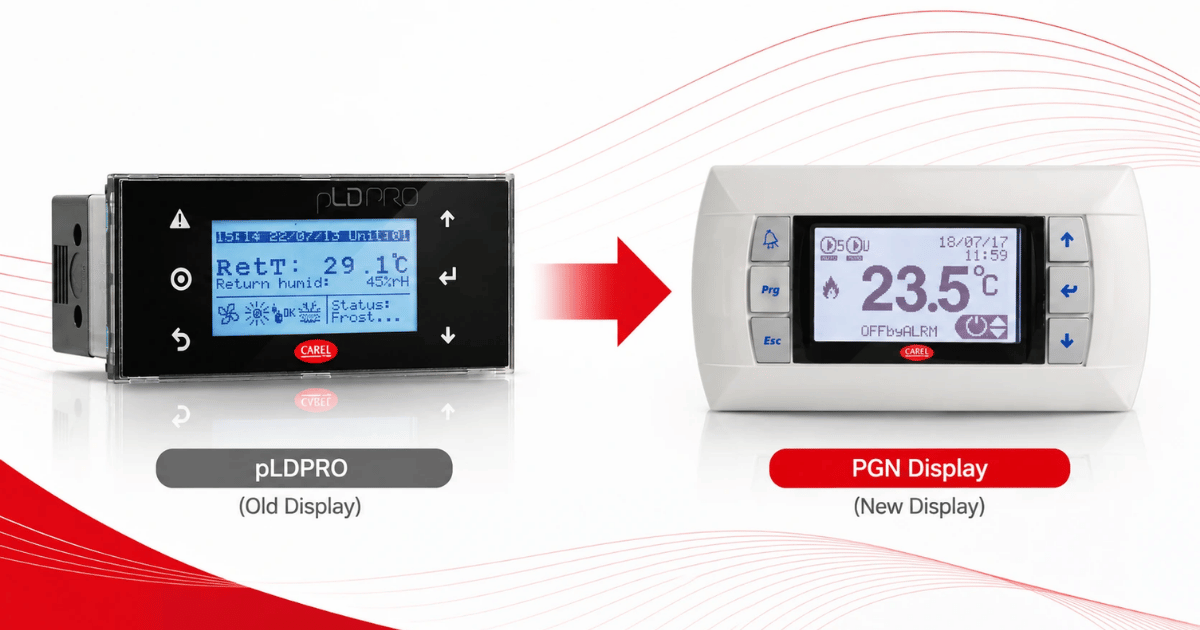
Replacing a CAREL pLDPRO Display: pGDn Options, Fit Checks and Affected Part Numbers
 September 23, 2026